(Trying to better explain the concept.) |
Tom Sponheim (talk | contribs) (Adding categories) |
||
| Line 52: | Line 52: | ||
[[Video:Solar design Jig and |thumb|300px|right|"Scallop shaped" may be too hard, simpler options are available.]] |
[[Video:Solar design Jig and |thumb|300px|right|"Scallop shaped" may be too hard, simpler options are available.]] |
||
Brian |
Brian |
||
| + | [[Category:Parabolic solar cooker designs]] |
||
Revision as of 18:21, 29 October 2013
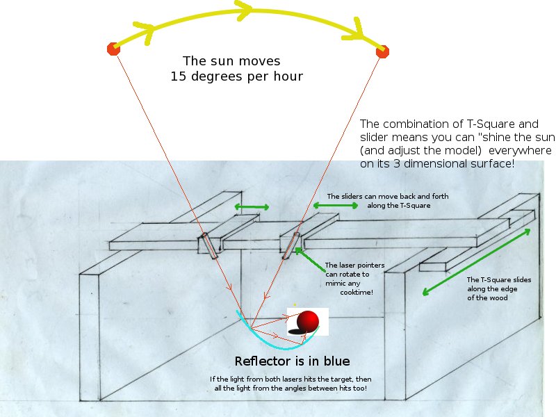
Summary: It is really hard to use the sun to adjust a solar cooker for good unattended cooking because the sun moves about 1 degree angularly every 4 minutes and because it shines everywhere at once. You cannot see the effect of an individual adjustment because it is drown out by all the other sunlight. By using a laser pointer to represent the sun, you can shine it on individual components and adjust them individually (like claymation) until the whole design works well at all the angles you require. This is a classic reverse engineering approach. The solar design T-Square is a simple device to represent the sun and greatly aids the design process. My aim is to design better solar cooker reflectors for unattended cooking. I imagine the sun as a giant spotlight shining down. It moves at about 15 degrees per hour across your solar cooker. The t-square could also be used to design box cooker rerlectors to catch more sun with side entry to the box!
The lasers are in line with the sun at the start and end of its path
In a couple of hours the path of the sun is pretty close to a straight line.
This means that you can use 2 laser pointers to represent the sun. One is for the sun at the START of the cook time and the other is to represent the sun at the END of the cook time. If you mount the laser pointers on a slider on a T-square, above your model, you can use them to test how the light rays bounce off of every part of your model! (something that you cannot do with sunlight itself because it hits every part of the reflector at once!) This means you adjust your model a little at a time, like claymation, until you get the desired result. Therefore you can make much better models of your new solar cooker reflectors and use the laser pointers to see where the light ends up after hitting the reflector. If the light bounces from your reflector and misses the target, it is a relatively easy task to adjust the reflector so that it hits its target.
Reflector shape made with the t-square
If you want a one hour cook time, you would set them to 15 degrees. 2 hours and 20 minutes of even powered cooking is impossible with an unattended parabolic solar cooker.
Dishes designed for unattended cooking with the tsquare are NOT parabolic dishes!
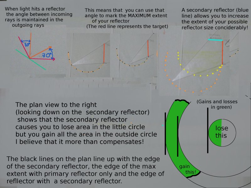
Why 2 bounces are needed when you make a reflector
This becomes apparent after 20 minutes using the device! Indeed, people will be able to use it to improve the performance of current parabolic dishes, giving them an extra few minute between adjustments, etc.thumb||
Using the T-Square, it should be relatively easy to design better cookit's and to design whole new ranges of solar cookers to better suit individual requirements. You can go for as much simplicity or perfection as your circumstances dictate!
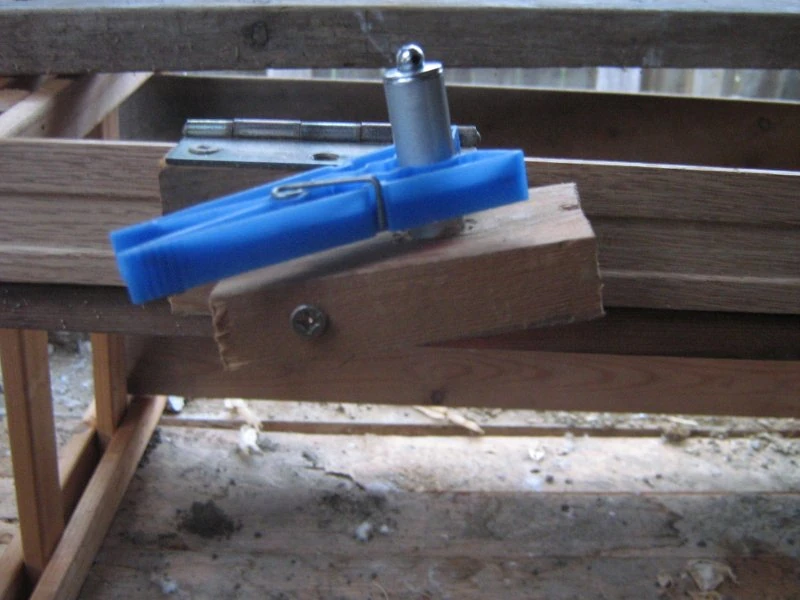
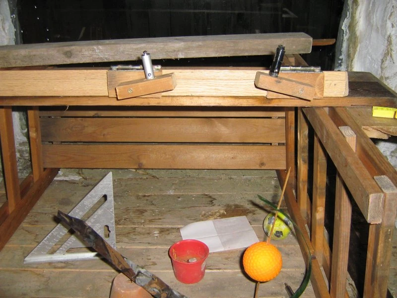
Clothespeg to keep the laser turned on
The clothespeg is necessary because the cheap laser pointers do not have an on off switch. They have a button that you must keep depressed.
The setsquare has degrees marked on it
I use mylar reflective plastic for the models. the Mylar is "stuck" to a plastic backing (a thin plastic table mat works) with water droplets from the sprayer. that is fairly easy. I also cut it into strips for the upright part that focuses the light further onto the ball. It is quite the task to keep them in place and that is a part that I have not figured out yet.
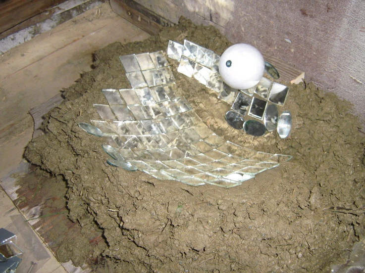
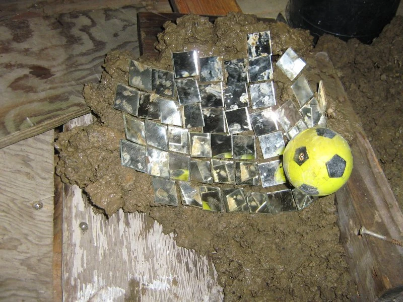
I have used the solar design t square to get the clam shape shown in the following pictures. The little mirrors are adjusted so that the light from each laser pointer hits the mirror and bounces to hit the target ball. I used clay underneath the mirrors to hold and adjust them.
Half the clam shape made with mirrors
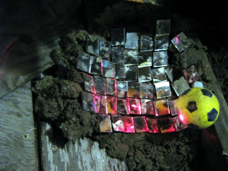
I also have pictures with the lasers on
The laser point hits the ball (target) and is reflected in the mirrors
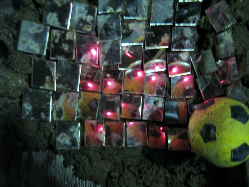
I have a pic of the overview too
The dots are the laser reflection from the ball
and here is the whole thing
The TSquare with the laser pointers turned on.
This is important to see how it is done
You can just see a laser dot on the bottom of the setsquare
Here you can see the laser spot at 75degrees
The steps to making a mold using mirrors and clay in this animated gif
When the clay mold is completed, the mirrors can be removed, the clay surface smoothed and the material for the real reflector put on the mold and molded to the shape. You can see a video of the earliest version of the designer at thumb|300px|right|"Scallop shaped" may be too hard, simpler options are available. Brian